
Brown University’s Sternlicht Residential Commons and Health & Wellness Center
 We spend much of our time indoors, but do those spaces make us happy?
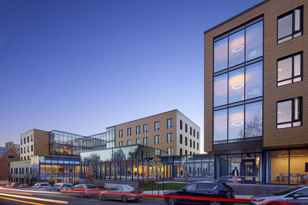
Brown University envisioned a new building, located at Brook Street in Providence, Rhode Island, that would bring together all aspects of health and wellness from the moment students wake up. The first new residence hall to open on campus in thirty years also houses the University’s Health Services, Counseling & Psychological Services, Brown Emergency Medical Services (BEMS), and bWell health promotion program. Yet the University went beyond promoting well-being with services and programs. Designed by William Rawn Associates of Boston, Massachusetts, the building itself is a warm, inviting composite of timber and glass that creates an uplifting and healing space. This project embodies the idea that health and wellness involve more than just eating your vegetables. Cold-pressed juices and designer athleisure apparel may not be enough to combat the gloom of cold, dark rooms. Add in the stress of group projects and studying for exams and it’s easy to see why students enthusiastically embrace the warmth of the new Sternlicht Residential Commons and Health & Wellness Center.
Biophilic Design: Greenspaces, Natural Light, and Wood Finishes
Timber helps provide a relaxing environment that eases stress and contributes to a happier and healthier place to live and study. LeMessurier engineered physical elements in the student common spaces, residences, and health programs to both support the building and bring nature inside. Floor-to-ceiling windows provide natural lighting and uninterrupted views of the green space of Pembroke Field across the street. Daylight playing off exposed wood finishes and natural materials elevates occupants’ moods and fosters a sense of well-being.
The project comprises two structures connected by a glass-enclosed walkway, with green spaces on either side. The north building features three suite-style residential levels above ground-floor common spaces, including a sun-filled lounge, a state-of-the-art communal kitchen, group meeting rooms, and a separate entrance lobby with bike storage for residents. The south building houses the University’s health and wellness spaces, with the pharmacy, ambulance bay, and bWell area at the lowest level. Exam rooms and offices for both Health Services and Counseling & Psychological Services are on the main ground level. The three residential levels above offer single, pod-style rooms with shared kitchenettes and large, open common areas. A multipurpose room offers a panoramic view, enclosed on three sides by full-height glass.
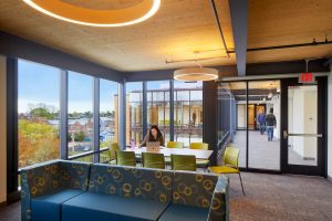
Figure 2: Interior residential common space with exposed CLT used for ceiling, photo by Bruce Martin
The ceilings of these dorm rooms and residential common spaces are exposed, cross-laminated timber (CLT) panels (Figure 2). Constructed of smaller lumber boards stacked in perpendicular layers and glued together, CLT panels provide significant strength, stiffness, and dimensional stability. In certain configurations, panels can be left exposed to serve as both the finish and the structure for floors, roofs, walls, and complete modular units, adding the warmth of timber and reducing the need for additional finishes.
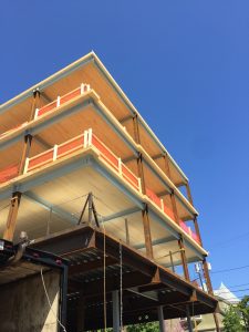
Figure 3: Under construction, photo courtesy of William Rawn Associates
Unlike steel and concrete construction, wood is a natural material and the strength, stiffness, and even visual appearance will vary depending on the species of trees used. CLT panels constructed of northwestern Douglas-fir, northeastern Black Spruce, or Southern Pine will each have different properties that could influence viable span lengths. Typical panel sizes are approximately eight feet wide by sixty feet long, but this can vary depending on the fabricator’s press and transport limitations. If the panels are shipped from Europe, they will be smaller and shorter to fit into shipping containers. The panels are typically constructed of three, five, seven, or more perpendicular layers of laminations with an overall thickness that depends on the fabricator. With this in mind, coordination is key to a successful project. Bay sizes and beam spacing can be optimized by engaging the CLT fabricator early in the project. This can help reduce costs by intentionally designing efficient systems that incorporate their specific panel sizes and reduce waste.
In the case of Brown, steel framing for the gravity and braced-frame lateral systems coupled with the CLT panels yielded a timber-steel hybrid structure (Figures 3 and 4). The first two levels are lightweight concrete on a composite metal deck designed to more easily achieve a two-hour-rated fire separation between the residence hall and health spaces.
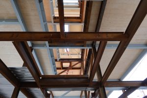
Figure 4: View through a stair shaft to levels above
Timber-steel hybrid structures are a marriage of traditional construction and green technology. CLT panels are not new to the building industry, particularly in Europe and on the West Coast of the United States; however, their adoption into US building codes is ongoing. CLT use in gravity systems first appeared in the 2015 editions of the International Building Code (IBC) and the National Design Specification for Wood Construction (NDS). CLT shear walls were added in the 2021 Special Design Provisions for Wind and Seismic and ASCE/SEI 7-22 Minimum Design Loads and Associated Criteria for Buildings and Other Structures. Code changes in the 2021 IBC sparked an increase in the use of timber in buildings up to eighteen stories. Between CLT fabricators, wood connector manufacturers, the American Wood Council, academic researchers, and resources such as WoodWorks, there is an increasing number of references and resources available for designing CLT structural elements.
Design & Construction
This design-build project, fueled by Brown’s desire for more on-campus student housing options and led by Shawmut Design & Construction, focused on a fast schedule. This schedule was further accelerated during the construction phase by the start of the COVID-19 pandemic. The steel-timber hybrid structure was selected to optimize the different structural elements for the design and construction process. The structure relies on traditional steel braced frames to carry the lateral load. Unlike a mass timber lateral system, the steel system did not require a variance to comply with the current building code, which would have led to a potential schedule extension. Steel construction is also more common than mass timber on the East Coast, so the learning curve for erecting the CLT panels had to be accommodated.
Using prefabricated elements generally increases construction speed and, despite the learning curve, prefabricated CLT panels are no exception. They are fabricated in a controlled factory environment that uses a computer numerical control (CNC) machine to ensure components fit once they reach the work site. Along with a high level of precision, this process decreases waste. The delivery of the panels is sequenced such that they can be picked and placed straight off the truck without the need for an extensive lay-down area, which is a benefit in tight sites. Fewer people are needed to catch and position a panel, and this “drop and go” process results in a solid walking surface, increasing safety. The hybrid steel and CLT system reduced erection time to complete the building structure by six weeks compared to a conventional steel building with composite slab on metal deck (Figure 5a).
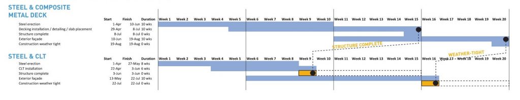
Figure 5a: Schedule comparison of hybrid steel/CLT to steel and composite metal deck, courtesy of Shawmut Design and Construction
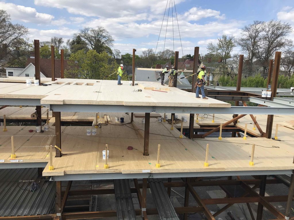
Figure 5b: CLT panel erection, photo courtesy of Shawmut Design and Construction
Nordic Structures, the CLT fabricator, provided five-ply panels that were roughly eight feet wide, up to 51 feet long, and had a thickness of just under seven inches. The typical layout consisted of three spans, each approximately fifteen feet long, but the CLT panels also worked well with the irregular column spacing in the south building.
CLT panels have a strong and a weak direction depending on the orientation of the laminations. The layers on the top and bottom of the panel are parallel to its length and define the panel’s strong, primary spanning direction. The cross-section shown in Figure 6 is cut through the width of the panels with the strong direction shown in and out of the page. The subsequent layers are rotated 90 degrees, allowing the panel to span in two directions. While advantageous for spanning around openings in all CLT buildings, this is required for point-supported CLT structures which, with closely spaced columns, eliminate the need for beams and create shallow floor plates. As creativity and innovation in mass timber continue to revolutionize the construction industry, we will benefit from the versatility of wood in our structures.
When coordinating the structure with mechanical, electrical, and plumbing (MEP) systems, the ability of CLT to span in two directions allows for the redistribution of loads around openings. If coordinated early, MEP penetrations can be located and precut with minimal effect on the panel’s structural integrity. While mass timber bears a close resemblance to precast concrete with regard to prefabrication, it is easier – for better or worse – to make field modifications. Delayed coordination may result in “Swiss cheese” panels that require additional sub-framing for support.
The CLT floor and roof structures served two primary structural functions. It spans between beams to support gravity loads and between lateral load resisting elements, such as braced frames, moment frames, or shear walls, to transfer wind and seismic loads. To act as a diaphragm and transfer lateral loads, panel-to-panel connections such as splines, half-lapped joints, or butt joints are required. Strength, stiffness, and ease of fabrication and installation vary with each connection type and should be considered in conjunction with input from the CLT fabricator. Resources, such as WoodWorks’ CLT Diaphragm Design Guides for Wind and Seismic Resistance, are available to assist in the design and detailing process.
Lessons Learned
Lessons learned in this project stemmed from both on-site experience and advice from Nordic. While anchoring steel to concrete has a long history, connecting timber panels to timber, steel, or concrete can be a bit challenging; the construction industry is actively developing and improving timber-to-timber, steel-to-timber and concrete-to-timber connections.
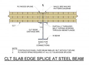
Figure 6: Consolidated detail for steel and timber connections
With CLT floor and roof slabs as the diaphragm, attention is needed to detail the connections. Nordic used their experience to steer the design away from a half-lap panel joint towards the plywood spline, citing better fit-up between panels and increased flexibility during erection (Figures 6 and 7). Several considerations for connections are shown in the consolidated detail in Figure 6. Note that the CLT edge joints do not typically coincide with locations of steel framing.
As shown in Figure 7, the panel-to-panel connection in this building utilizes a surface spline where the top of the CLT is routed along the edge to fasten the plywood with nails. The spacing of the nails or screws varies depending on the shear force demands in each area of the diaphragm. The capacity of this connection depends on the spline, fasteners, and reduced CLT section. In structures with higher lateral loads, a steel plate can be used in lieu of plywood.
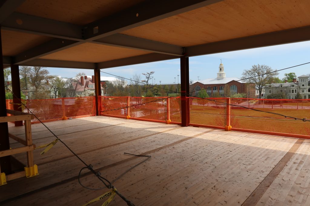
Figure 7: Plywood splines connecting adjacent panels
A typical CLT panel-to-glulam beam connection uses self-tapping screws that pass through the panel into the beam below. The connection between CLT panels and steel beams is similar, but the screws are installed from below, through the top flange of the steel beam (Figure 8). Along with bracing the top flange of the beams, these connections allow the steel framing to act as drag struts to the steel braced frames and the diaphragm chords. As with the spline nailing pattern, the screw spacing can be varied depending on demand, but must comply with minimum spacing requirements.
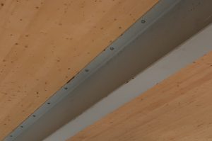
Figure 8: Self-tapping screws through the top flange of the steel beam
When the width of a building exceeds the length of the CLT panels, end joints will be present in the panel layout. With the joint between panels centered on the beam, the screw holes in the top flange must be spaced sufficiently to avoid splitting the wood and comply with the end distance requirements. Similarly, if an end joint coincides with a steel beam, the hole spacing must comply with edge distance requirements.
Since designing the steel framing preceded decisions about the panel layout, the team decided to provide wide enough beam flanges to allow any beam to accommodate a panel joint. Additionally, due to limitations on the placement of columns and braces in the health spaces, the framing formed an irregular grid. The flexibility of the timber-to-steel connections facilitated the smooth coordination and construction processes.
Another important takeaway is to coordinate screw hole sizes with the steel fabricator. Since the connectors are loaded in shear, a 3/8” diameter screw won’t function in a hole sized for a 1/2″ diameter connector. Increasing the screw size sounds straightforward – a bigger screw equals more strength – but for ductility, it is recommended that the yielding of the fasteners govern the design. Additionally, a larger screw results in larger edge distance, end distance, and spacing requirements.
The perimeter and corners of CLT floor plates present unique challenges. Curtain wall wind anchors, typically connected to steel beams or plates at concrete slab edges, were screwed into the edges or “side faces” of the CLT panels. NDS gives spacing requirements and capacity reduction values for screws installed in the side faces of CLT panels, either in the end-grain or edge-grain laminations.
Mass timber construction is a straightforward process involving the repetitive erection of single-story columns, beams, and panels. Steel columns are typically spliced every couple of stories, which creates a Tetris-like challenge for erectors to work around. Ocean Steel & Construction reviewed the original column schedule and requested that the splice locations be adjusted to help simplify panel erection. The panels were shipped to the site with precise cut-outs to fit around columns and braced frame gusset plates. Additional infill pieces of CLT were added at columns around the perimeter and corners of the building to maintain a consistent slab edge. These pieces were screwed into the main panels at the edge columns and additional support angles were provided at the corner columns.
Deciding on Mass Timber
There are reasons a project may consider including mass timber construction beyond the benefits of visually exposing the timber structure. Two of the primary positive impacts relate to resilience and sustainability. Timber construction offers the green benefits of supporting managed forestry and using a renewable resource that sequesters carbon. A recent focus on reducing embodied carbon of structures is reflected in the SE 2050 Commitment Program (SE 2050) of the American Society of Civil Engineers (ASCE).
Add in all the other pieces to complete construction, and this steel and timber skeleton becomes a building that reaps the biophilic benefits of wood for residents and visitors alike. Opened in May 2021, the connection to nature is evident in the reflection of trees on the glass wall of the multipurpose room and the illumination of the CLT ceilings in the common spaces of the residence halls.
Project Team
Architect: William Rawn Associates
Structural Engineer: LeMessurier
Contractor: Shawmut Design & Construction
CLT Fabricator: Nordic Structures
Steel Fabricator: Ocean Steel & Construction
Concrete Contractor: Marguerite Concrete Contractors